 The newsletter of NASA's Radio JOVE Project
"Solar and Planetary Radio Astronomy for Schools"
The newsletter of NASA's Radio JOVE Project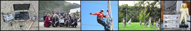
We are two seniors at Thomas Jefferson High School for Science and Technology in Alexandria, Virginia. During the 2005-2006 school year, we have been continuing a three year Radio JOVE project to collect signals from the galactic background. This is actually the first year that a team has been able to collect data; the prior two teams spent their time constructing the telescope.
We entered our project in the local science fair and progressed to the regional level amongst steep competition, finishing with second place in our Earth & Space Science category and a first place award from the National Space Club. One of the differences in our project compared to the other projects at the Fair was the fact that our project was based on research, not experimentation. The main goal of our project was to collect and analyze data, but it quickly became more of a priority to analyze the telescope itself.
We began this project with little prior knowledge of radio astronomy. The original difficulties of this project were not in comprehending complicated theories and formulas in college level textbooks. Instead, we faced problems with simple tasks such as tying knots, adapting our equipment to the weather, preparing electronics, and more importantly, understanding the errors we saw in our data. Although it was easy to find information about the signals we were supposed to pick up, we could not figure out what we were doing wrong until we contacted a member of the JOVE community, Mr. John Avellone.
Several of the errors we encountered included:
Although we will not be able to continue this project, we are passing it on to another team of rising senior students for the 2006-2007 school year. We hope that they will be able to perfect the structure and efficiency of our rooftop telescope, as well as finally be able to collect solar and Jovian signals in addition to the galactic background. Their upcoming school year will be a prime time for solar activity, and we hope that they will be able to capture the effects of solar flares. While we were faced with the challenges of the telescope, from its set-up to its data collection to recognizing errors, we have nonetheless not only gained knowledge and appreciation for radio astronomy, but also improved our telescope for future TJHSST teams.
Beginning in March 2005, Dr. Chuck Higgins began observing the Sun on a daily basis with a standard dual dipole and a Radio JOVE receiver. High school students Kacey Jo Hathaway and Jennifer Hamilton, along with their teacher Heather Corbin, from Wilson Central High School began to analyze the data. We analyzed the data for long-term trends of solar bursts recorded at 20.1 MHz, specifically to see how the number of detected solar bursts compares with the sunspot number.
MTSU undergraduate students Monica Villarreal and Philip Mason have continued recording, compiling, and analyzing the data through February 2006. The graph shows the combined data averaged every 15 days for 11 months. There is a reasonably good correlation between our solar storm counts and the sunspot number. As you know we are currently at solar minimum; therefore the total number of bursts received is very low and thus requires some averaging.
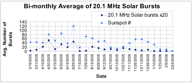
We are currently adding more data to the plot, and we are even going back and using some data gathered from a faithful RJ listener Mr. Jim Brown of Beaver, PA. We also plan to extend the analysis to include information about the intensity and duration of the bursts as a function of time. We hope to continue adding data to the plot and build up a long term set of data for a complete solar cycle.
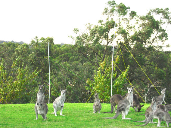
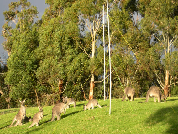
[Editors note: We received from one of our team members these great photos and a description of his Radio Jove system. We would love to have others share photos and descriptions of their setup as well. Please send them to us at rj_project@radiojove.gsfc.nasa.gov
antenna:
feeds:
receiver : Jove receiver on 20.1MHz
software : SkyPipe 1.3.1
location : Melbourne/Australia (55km from the CBD)
name : meljove01 (Melbourne Radio Jove)
coordinates: 38.01 S/145.24 E
The Agawa Jupiter Radio Observatory (http://jupiter.kochi-ct.jp/agawa/) began operation at the beginning of 2006. We had an opening ceremony for the observatory on January 19th with special guest Dr. Jim Thieman, leader of NASA's Radio JOVE project.
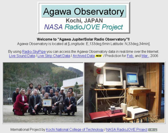
Agawa Observatory is located at East Longitude 133deg, 6min and North Latitude 33deg, 34min. Agawa was one of the names of the villages in Kochi Prefecture located at Shikoku island, Japan. Niyodogawa is the new name of the town. Mr. Toshimitsu Ohno who is a superintendent of schools in Niyodogawa, is a promoter of the Radio JOVE project in Kochi. He and I successfully installed a Radio JOVE antenna and receiver.
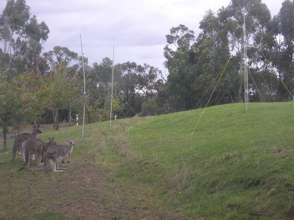
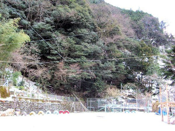
We are using a standard dual dipole array antenna without masts. The photo shows the structure of the wired antenna system. The observing frequency of the Radio JOVE receiver is 20 MHz. The local electromagnetic noise is very low around the observing site.
Now we are broadcasting the sounds of the Radio JOVE receiver output (http://sound.kochi-ct.jp/agawa). You may hear the sounds of Jupiter all the way from Japan. Agawa Observatory also started to stream the Radio JOVE real time data by SkyPipe. You may find Agawa Observatory listed while using SkyPipe in client mode.
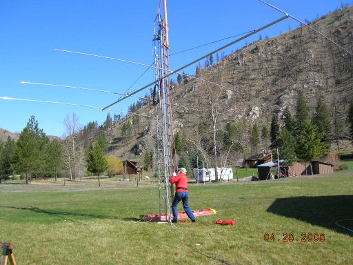
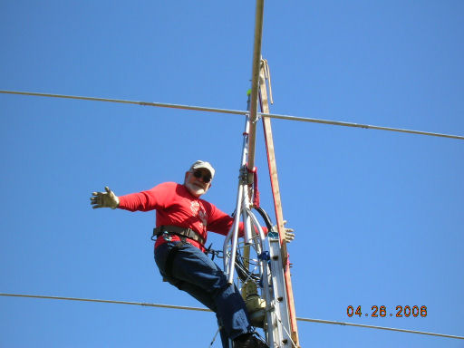
[Editors note: Dusty Samouce recently sent around a couple of emails and several photos describing the system he has in place at his radio observatory in Montana, USA. For your enjoyment we are presenting an article in the Bulletin based on his descriptions. It looks like an incredible installation. Thanks for the tour, Dusty!]
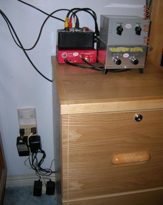
The Samouce Solar Facility is located in western Montana (46N/114W) at 4220' (1286 meter) altitude. See Figure 1 for an overall view of the Radio Section system.
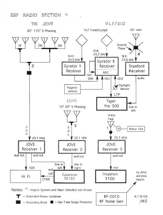
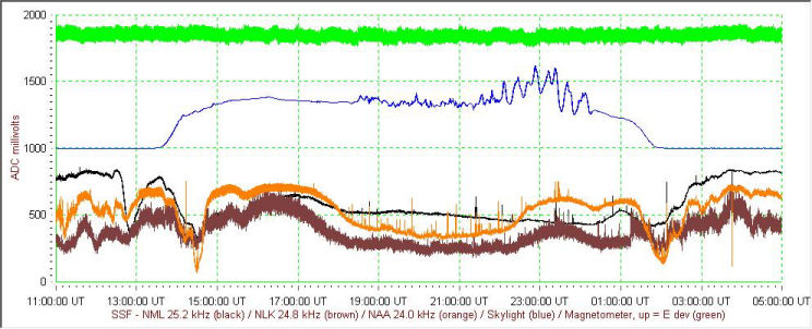
Very Low Frequency/Sudden Ionospheric Disturbance (VLF/SID) System: Two Gyrator II receivers (http://www.aavso.org/observing/programs/solar/gyrator.shtml) are shown in Figure 2 as the gray and silver boxes. The silver box contains a Gyrator II receiver with the power supply which it shares with the other receiver, it also contains a MAX 186 based ADC from Radio Sky Publishing (http://www.radiosky.com/max186purchase.html). The red box is a Stanford SID Monitor (http://solar-center.stanford.edu/SID). The black box contains the electronics and interface to the Skylight sensor and Magnetometer (http://www.regulusastro.com/regulus/papers/magnetometer/index.html). The Radio SkyPipe sample chart (see Figure 3) shows an orange trace - NAA (2200 miles east) at 24.0 kHz from a Gyrator II with tuned loop antenna and no bias; black trace - NML (680 miles east) at 25.2 kHz from a Gyrator II with tuned loop antenna and + 200 bias to get it out of the "traffic jam"; brown trace NLK (360 miles west) at 24.0 kHz from Stanford SID Monitor (audio output to computer sound card) with 20 foot vertical antenna with -152 bias (set such that trace would go to zero with antenna disconnected); blue trace - Skylight sensor pointed to northern sky with +1000 bias to get it away from the VLF traces; green trace - magnetometer with no bias.
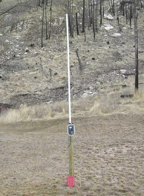
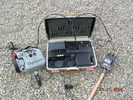
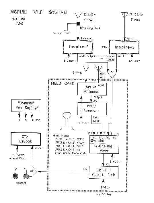
INSPIRE System: Figure 4 shows the Inspire-2, as "Base Station", with fixed ground and 10 foot vertical antenna. This can only be used during power outages (which happens here all too frequently) because of overwhelming 60 Hz background. The spade mounted Inspire-3 receiver (see Figure 5) (http://image.gsfc.nasa.gov/poetry/inspire/index.html), as "Field Station", is to be carried to the mountain tops. The spade (blade outside of the picture) is a convenient ground and also supports the receiver on its handle. The diagram (see Figure 6)shows the INSPIRE system interconnections.
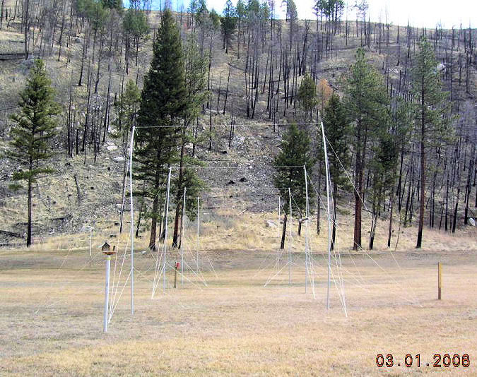
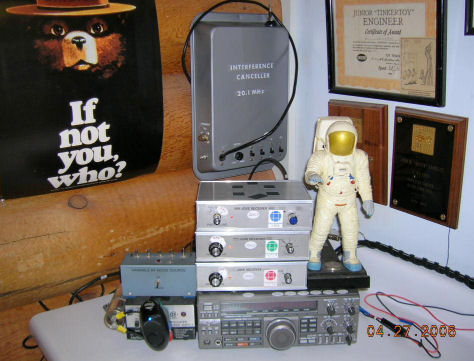
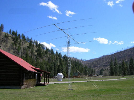
Radio JOVE System: Consists of three antenna arrays to three JOVE receivers to two computers. The pictures (see Figures 7, 8) show the antenna arrays and receivers. In the picture with the Yagi (Figure 9) note the clamshell dome in the background that houses the optical solar telescopes (6"/f10 and 2 1/2" Ha refracters). The monoband M^2 15M4DX Yagi (http://www.m2inc.com/index2.html) has been modified by extending the elements by 4% to tweak it from 21.0 to 20.1 MHz (21.0/20.1 = ~ 1.04). The extensions are pieces of 1/4" copper tubing (aluminum would be better but the copper was on hand). The Yagi tower is a 22' AME 25 from American Towers, Inc (http://www.amertower.com/amerite_towers.html) (see installation pictures Figures 10, 11). Now if only my local power line buzz would go away! Waiting for some good Io passes.
You may have noticed that the Radio JOVE website has a brand new look. We hope that you will find the new structure and layout easier to navigate. We've used the occasion of this redesign to make important updates and additions to our content, such as the new Sample Data page, and the writeups on setting up and testing the RJ 1.1 radio telescope.
If you cannot find what you are looking on the new site, want to report problems, such as broken links, or just want to give us feedback on the new look of the site, please drop a note to rj_project@radiojove.gsfc.nasa.gov.
In July 2006, the Radio JOVE team will have a "changing of the guards", so to speak. Mr. Bill Pine will be relinquishing his role as the RJ kit distributor and passing the duties on to Chuck Higgins and the MTSU astronomy club. Bill will be focusing on the INSPIRE Project, a project which he co-founded. Bill and INSPIRE, Inc. were really instrumental in the creation of the Radio JOVE project because they already had the foundation in place to handle kit parts, ordering, and shipping. During the last 7 years, Bill has helped Radio JOVE distribute more than 850 kits! Incredible! He worked closely with Mr. John Kohus to package all the 100 parts in bags, and then was able to use his physics students to help him box up the wire, cable, insulators, and manuals, and then ship them to places worldwide.
Thank you Bill for your dedication, hard work, friendliness, generosity, and honest-to-goodness sharp-mindedness that helped make this project work. Fortunately Bill will still be involved with Radio JOVE in other ways.
The daunting task of following Bill's great work and high standards has fallen to Chuck Higgins and a team of undergraduate astronomy club students. Wes Greenman has bravely volunteered to shoulder John Kohus' role. Sometime later this summer you will notice that kit orders will be sent to Chuck at MTSU. We hope this transition will be as smooth as possible. Stay tuned for more details.
The JOVE Bulletin is published twice a year. It is a free service of the Radio JOVE Project. We hope you will find it of value. Back issues are available on the Radio JOVE Project Web site, http://radiojove.gsfc.nasa.gov/
For assistance or information send inquiries to:
or
Email: rj_project@radiojove.gsfc.nasa.gov