 The newsletter of NASA's Radio JOVE Project
"Solar and Planetary Radio Astronomy for Schools"
The newsletter of NASA's Radio JOVE Project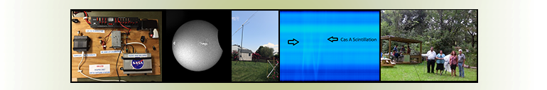
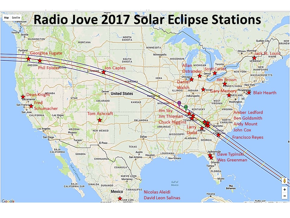
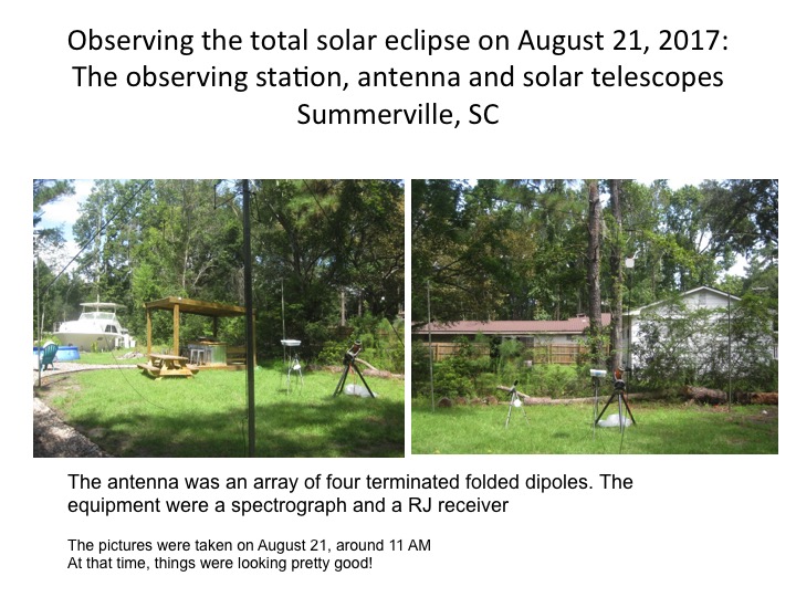
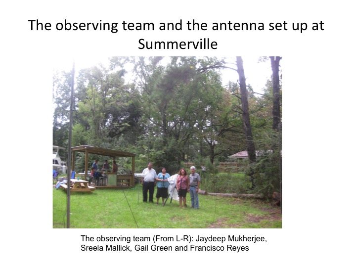
On 21 August, 2017, North America experienced a total solar eclipse. Millions of people witnessed the spectacle and among them were a group of intrepid Radio Jove participants. Radio Jove team members have been preparing for over a year for this auspicious day. The June 2016 Jove Bulletin announced our plans for the eclipse and encouraged all members especially our North American observers to participate in a series of teleconferences to refine their observing techniques. For months dedicated observers were submitting Galactic Background scans to the Radio Jove Archive for use as a baseline for comparison to any changes in background levels observed on the day of the eclipse. These months of preparation and discussion also helped observers combat the ever-present radio frequency interference which is a common issue for everyone making radio observations. Finally the big day arrived and Radio Jove observers were in place at locations across North America (see the map below). The data submitted to the archive before, during, and after the eclipse are being analyzed now to determine what changes in Earth's ionosphere may have been observed during the eclipse at the Radio Jove operating frequency (about 20 MHz).
In this first article in a series we feature a few of the Radio Jove observers and their experiences.
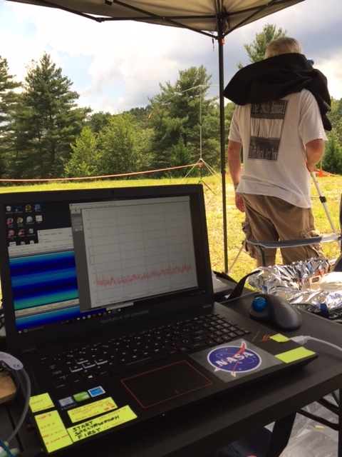
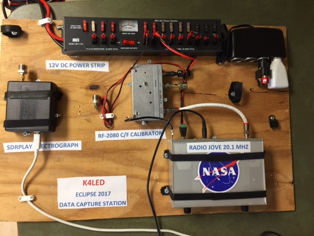
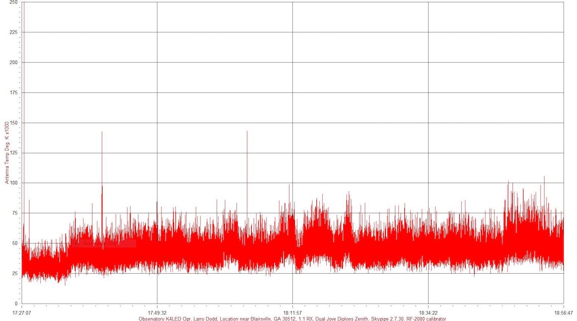
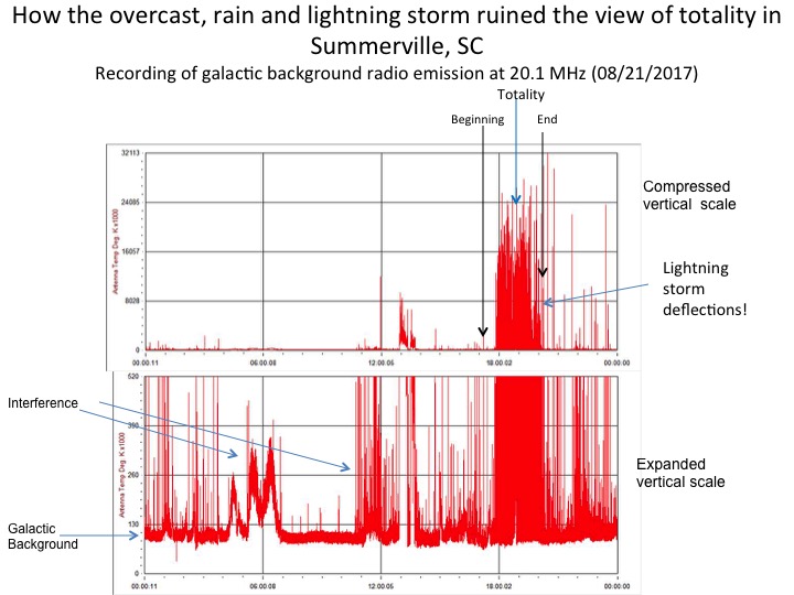
K4LED, Larry Dodd, set up an August 2017 remote eclipse radio astronomy station consisting of a Radio Jove R1.1 20.1 MHz single frequency receiver and a Radio Jove dual dipole. An SDRPlay 1, software defined radio, was used to capture spectrograph data from a single dipole. All equipment was battery powered. The station was located in Meeks Park just west of Blairsville, Georgia. Radio conditions were good and the weather cleared during the total eclipse. Shortly after totality a heavy rain shower moved in and the station had to be taken down quickly. Luckily no lightning occurred before or after the event. The total eclipse was spectacular and all concerned were glad they made the effort to view the total eclipse even though at our location it only lasted less than 2 minutes. Two friends assisted in setting up the radio telescope, tent, and equipment. It was great fun and we learned why many people travel great distances to see a total eclipse. It is spectacular. We had 2 minutes of total eclipse time. Clouds cleared just in time for a spectacular visual view. We could distinctly see baileys beads, the diamond ring, and the total eclipse corona. The difference between a total eclipse and a partial eclipse is like night and day, literally. Many visitors stopped by to ask about the station and the Radio Jove program. Each received a handout to explain the NASA outreach program. A home radio astronomy station in Jasper, Georgia recorded the event as well, unattended.
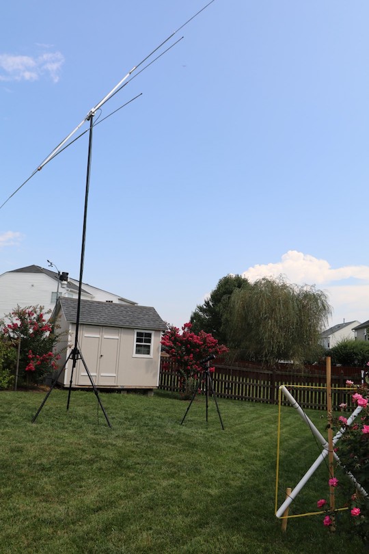
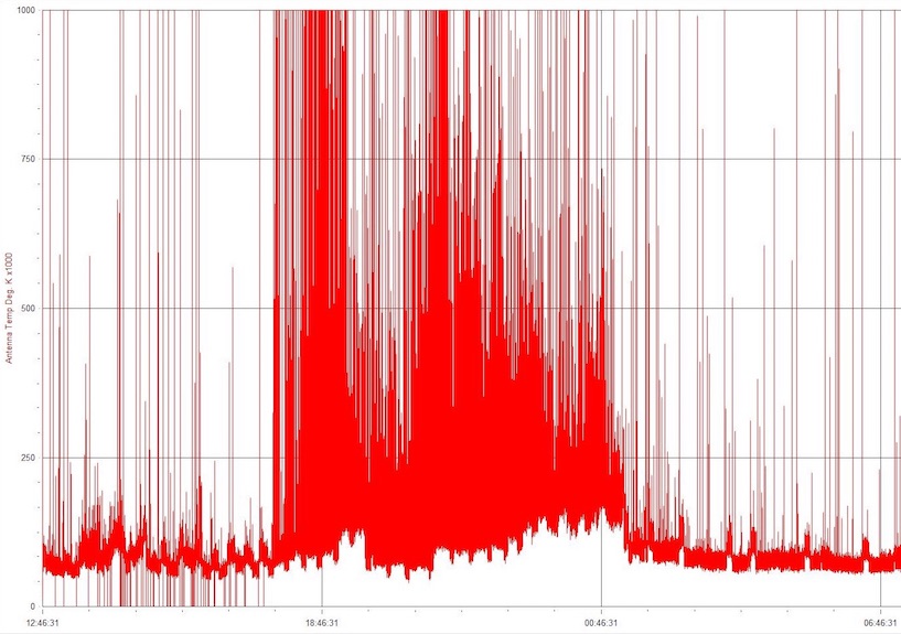
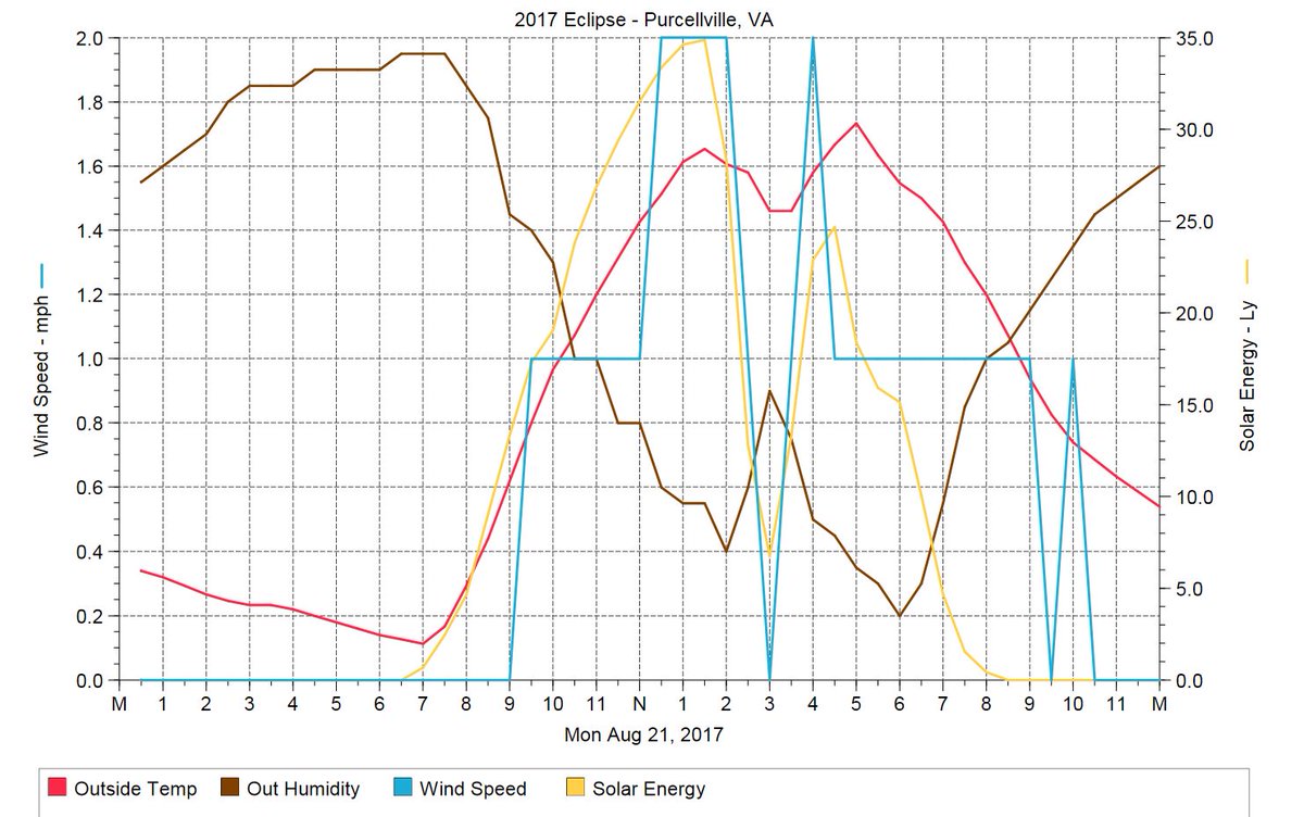
My wife Carla and I had fun on the day of the 2017 Eclipse. We gave it our best shot with various radio, visual and weather based observations from our home here in Purcellville, Virginia. While we live in a farm based rural setting, our specific neighborhood consists of newly built, densely packed houses. Despite living in "cow valley" (as our daughter calls it), our RF environment is a virtual cesspool. Between modern appliances, LED lighting, wireless everything (to include doorknobs and light switches, and more it seems)....etc, finding a quiet spot in the radio spectrum is often a futile effort. And such was the case for our effort to monitor the eclipse. That coupled with a strict HOA that refuses to allow any kind of antenna, whether it is approved by the FCC or not. Their stance is, even if you can provide a law supporting your antenna, "we will see you in court!"
While I am often able to calibrate Radio-SkyPipe below 80K degrees Kelvin, our average noise floor is often much, much higher. Using my Solar/Jove receiving equipment I can usually very easily discern when this or that appliance is turned on in a neighbors house. Alas, on the day of the eclipse we had copious RF noise plus I was required to depart on business travel shortly after Solar minimum or maximum moon coverage for our location. Nevertheless, we gave it our best shot. Experiments or eclipse activities in our back yard included: Radio Jove at 21.1 MHz, SuperSID receiver (six VLF frequencies), ambient weather and photography via a 600mm lens/solar filter.
My JOVE receiver setup is a bit abnormal, but I wanted to see how well or if it would work at all. My equipment included: HyGain 3-element Yagi Mono-band antenna on a portable mast, ICOM IC-R75 Receiver, Roland Quad Capture Sound input to laptop, Radio-SkyPipe Pro.
Attached are a couple photos of our efforts. Alas, not much scientific knowledge was gained. But it was fun!
Gary Memory, N7BRJ
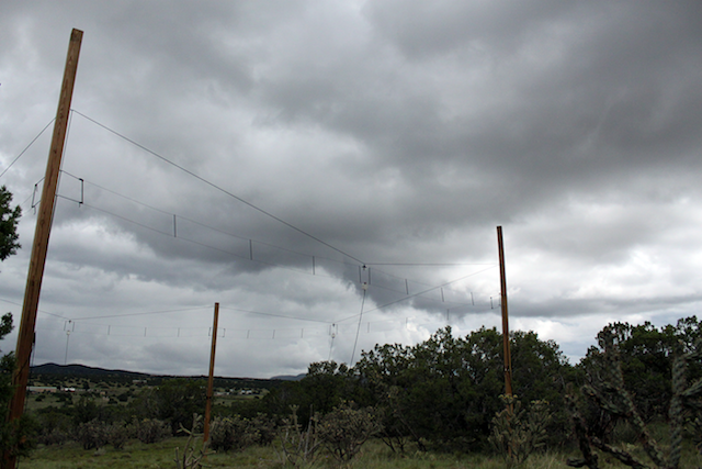
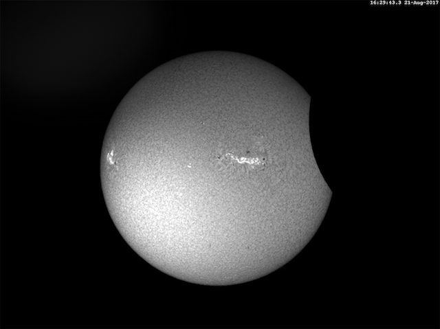
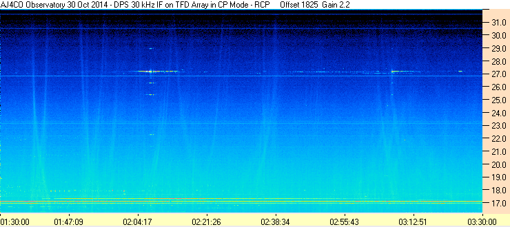
It was cloudy for the most part here in New Mexico during the eclipse but radio reception with my TFD (terminated folded dipole) antenna array was not affected. Here also is a hydrogen-alpha view through my optical solar telescope at 1629 UT. Note the active sunspot group which created ongoing solar radio bursts throughout the day. Here is my radio spectrogram for around 1629 UT which shows very active solar emissions.

[Editor’s Note: This is a greatly abbreviated version of the original article. The complete article is available on the Spectrograph Users Group (SUG) website.]
An article, “Jupiter on Your Shortwave”, written by David Rosenthal[1], was published in the December 1989 issue of Sky & Telescope. The article describes a small wire loop antenna, attributed to a design by Bob Sickels, and suggests using this antenna for hearing signals from Jupiter. The plans for building this antenna have found their way onto the internet and many folks have built it. We have performed computer modeling as well as on-the-air, side by side testing of this, so called DDRR (Direct Driven Ring Radiator) antenna, with the Radio Jove dual dipole array. The Jove antenna proved to be vastly superior. Using the Rosenthal wire loop antenna, we were barely able to detect very strong Solar bursts and no Jupiter signals. While we encourage antenna experimentation, our testing results show that this antenna is not suitable for radio astronomy. Despite its small size and ease of construction we do not recommend it for anyone hoping to hear Jupiter.
The small wire loop is similar to at least one form of the DDRR (Direct Driven Ring Radiator) antenna reportedly invented by Dr. Boyer in the 1950s. Rosenthal’s article provides dimensional specifications for the construction of this antenna for use at 21 MHz. We have built and tested the performance of this antenna in comparison to the Jove dual dipole array.
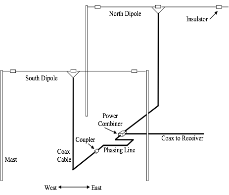
The Radio Jove project recommends a dual dipole array (Figure 1) for listening to Jupiter on 20.1 MHz. This antenna has the disadvantage of requiring a clear space, 30 feet by 45 feet, to set up. Unfortunately, many folks interested in Radio Jove often don’t have enough room for the antenna.
The small wire loop antenna seems an attractive alternative to the much larger dual dipole array. This tiny loop antenna (Figure 2) has attracted many observers over the years. And why not – it is only 2 feet square and very simple to construct.

Richard Flagg and I decided to do a side by side test of this tiny loop antenna and the Jove dual dipole array. If it worked as a limited space alternative to the much larger Jove antenna that would be great. Following the Sky & Telescope instructions, the antenna was constructed (Figure 3) and compared with a standard Radio JOVE dual dipole phased array over the course of a year. Observations were made of both Solar and Jupiter events using single frequency receivers and Radio-SkyPipe software.
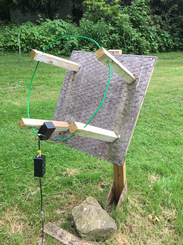
Construction of the loop antenna (Fig. 3) followed the specifications of the article. The antenna was fed with RG8X coax which had a measured loss of 1.1 dB into an Icom R75 receiver, which had been previously adjusted to produce its maximum dynamic range. The beam pattern for the tiny loop antenna was modeled and found to point essentially at right angles to the direction in which one would aim the loop. Details on the modeling can be found in the full article.
A simple matching network was constructed to present a better match to the receiver. The antenna was positioned in proximity to the JOVE dipoles and was tilted to 50 degrees, the elevation of Jupiter at transit at my observatory.
While the sun has been relatively quiet, and Jupiter’s southern declination is less than ideal, several solar bursts and Jupiter storms were observed over the course of the year allowing us to draw some useful conclusions.
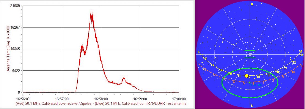
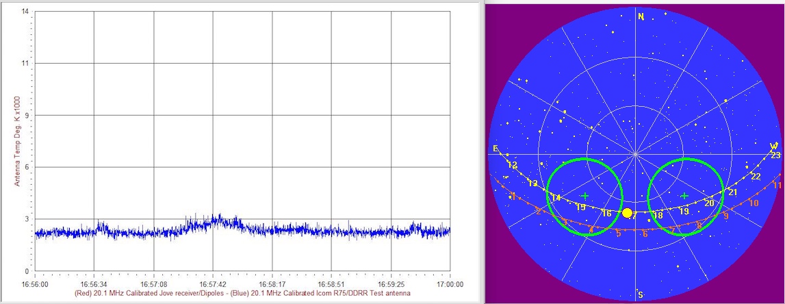
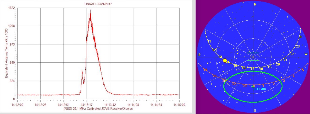
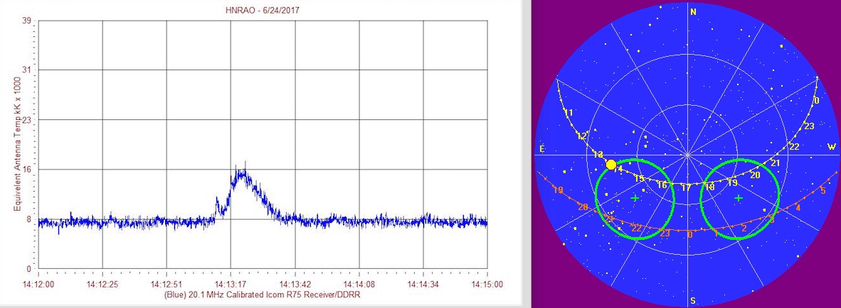
The Jove antenna typically measured a galactic background temperature on the order of 65 kilokelvin (kK). At the same time, the DDRR yielded galactic background temperatures of less than 3 kK. This is interpreted to mean that the DDRR is very inefficient, on the order of a few percent efficient. This is not surprising for such a small antenna with very low radiation resistance and high capacitive reactance. Ohmic losses in the loop apparently far exceed the radiation resistance. The consequence is that very weak signals are delivered from the DDRR. It is possible that a very low noise preamplifier at the DDRR terminals could help.
The DDRR failed to receive any identifiable signals during periods of moderate strength Jovian radio noise storms. A solar burst that rose 24 dB above the galactic background on the Jove dual dipoles produced a deflection of approximately 0.7 dB on the DDRR.
It is unfortunate that the tiny loop antenna has crept into the literature as a limited space antenna that can be used successfully for reception of solar and Jovian signals.
Real world, side by side comparisons, of antenna performance are of real value. When something looks too good to be true it usually is. Unfortunately, novice observers often are unable to distinguish between a good and bad design.
The authors point out that there is currently some uncertainty regarding the provenance of the antenna described in Sky & Telescope. That is the one which we tested and refer to as the DDRR. Is this truly a Bob Sickels design as Rosenthal states, or can it be traced back to some earlier observer? Did Bob recommend a larger loop, perhaps a quarter or half wavelength long – some say he did. Regardless of the exact history – our goal was to test the antenna described in Sky & Telescope and that is what we have done.
The continued use of the antenna as described in Sky & Telescope can only serve to discourage new amateur radio astronomers wishing to participate in the Radio JOVE project and other radio astronomy endeavors.
Finally, we want to stress that the Radio Jove program encourages antenna experimentation in the hopes of being able to accommodate more observers who are challenged for antenna space. The quest continues.
[1] “Jupiter on Your Shortwave”, D. Rosenthal, December 1989, pp. 628, Sky & Telescope
[Editors Note: This article is a follow-up to an article published in the January 2015 Jove Bulletin.]
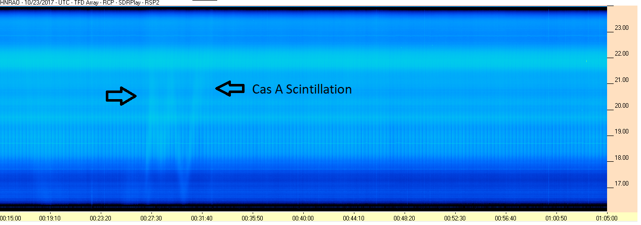
The Jove radio telescope has been used for many years to detect signals from Jupiter, the Sun, and the galactic background. Several Jove team members operate spectrographs in addition to the standard Jove receivers. During nighttime spectrograph observations as far back as 2013 Typinski, Ashcraft, and Greenman observed faint whispy semi-vertical bands of emission on some spectrograph records (2014).[1] Ashcraft suggested that these emissions might be scintillation of Cassiopeia A (figure 1.) or Cygnus A, and noted similar scintillation events observed by the KAIRA research instrument in Finland.[2] When Typinski steered his 8-element antenna array toward Cas A the features became much stronger, supporting the belief that the source was indeed Cas A (fig. 2).
We have attempted to expand on the work done by Typinski, Ashcraft, and Greenman to show that Cas A scintillation can be observed using a simple Jove dual dipole and a Jove receiver.[3]
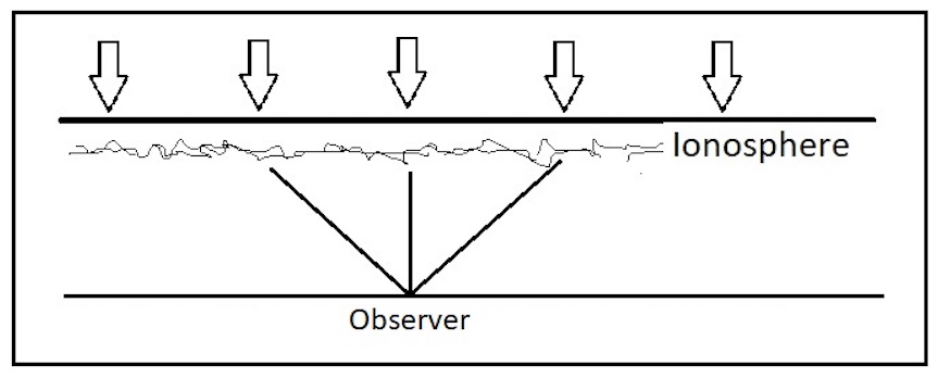
Cassiopeia A is the strongest source of radio emission in the sky beyond the solar system. Located in the direction of the constellation Cassiopeia about 11,000 light-years from Earth, Cas A is the remnant of a supernova explosion caused by the collapse of a massive star. High frequency radio waves emanating from Cas A, pass through the Earth’s ionosphere where they encounter a non-homogeneous mix of free electrons (fig. 3). Signals are refracted, causing numerous signal paths to converge on the observer’s antenna. Phase and amplitude variations of these multipath signals cause scintillation, resulting in either an increase or decrease in signal strength. The result, viewed by a high frequency radio spectrograph using a relatively small antenna is seen as wispy semi-vertical emission bands slightly above the galactic background (GB).
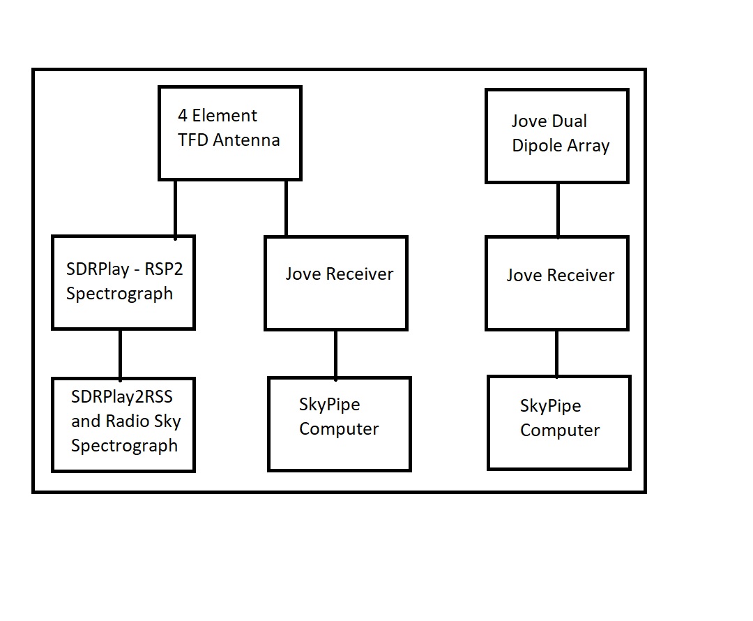
Radio spectrograms were captured with a terminated folded dipole (TFD)[4] 4-element array using the SDRPlay RSP2 spectrograph (http://www.sdrplay.com/). Right hand circular (RCP) polarized signals from the array were processed for display using Nathan Towne’s SDRPlay2RSS and Radio Sky Spectrograph software[5]. In addition to the spectrograph, a 20.1 MHz Radio JOVE receiver was connected to the TFD antenna. A second Jove receiver was connected to a standard linearly polarized Radio JOVE dual dipole array. Audio outputs from both Jove receivers were used to produce Radio-SkyPipe (strip chart) records.(fig. 4) The TFD and Jove antenna beams were aimed north at an elevation of 63 degrees.
Observations were made at Hawks Nest Radio Astronomy Observatory (HNRAO) located in Industry, Pennsylvania (40.673N, 80.438W).
Signals were recorded during nighttime observations of Cas A between the 23rd and 25th of October 2017. Three of the most visible scintillation events were selected from the spectrograms. These events were identifiable in both the TFD Array and the JOVE Radio Telescope Radio-SkyPipe records.
Prior to the observations, both Jove receiver systems (operating at 20.1 MHz) were calibrated with a common noise source using the Calibration Wizard feature of the Radio-SkyPipe software. This calibration allows the observer to determine antenna temperature in kilo Kelvin (kK), referenced to the antenna feedpoint. In order to reduce the magnitude of statistical fluctuations in the strip charts, Radio-SkyPipe (version 2.7.30) [5] records were post-processed using “Find Lowest Point” with a bin size of 10 and “Smooth by Average” with a bin size of 10. The antenna temperature (largely due to the galactic background) was measured immediately before and after each scintillation event. These measurements were averaged to estimate the GB temperature at the time of the scintillation event. Then a measurement was made at the peak of the scintillation event. The ratio of the scintillation peak to the average GB was then calculated and expressed in decibels (dB). Data are presented in tabular form (Table 1).
Since Cas A scintillation is caused by the ionosphere, the intensity of scintillations can vary from night to night. Also, the antenna temperature which is predominantly due to the galactic background at a radio quiet site, varies from night to night due to some amount of radio frequency interference (RFI). Analysis of the Radio-SkyPipe records indicates that some of the most prominent Cas A scintillation peaks were on the order of ½ dB above the galactic background temperature.
| 2017 | TFD | Jove Dipoles | |||||
|---|---|---|---|---|---|---|---|
| Event | Date | GB Avg kK | Cas A peak kK | dB rise | GB Avg kK | Cas A peak kK | dB rise |
| 1 | 10/23 | 93 | 102 | 0.40 | 91 | 98 | 0.32 |
| 2 | 10/24 | 83 | 96 | 0.63 | 95 | 112 | 0.71 |
| 3 | 10/25 | 91 | 106 | 0.66 | 87 | 95 | 0.38 |
Data for each of the events listed above are presented below (figs 5, 6, and 7).
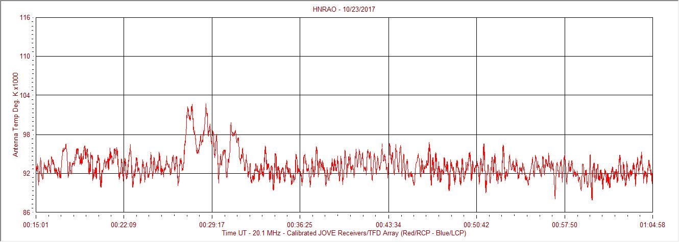
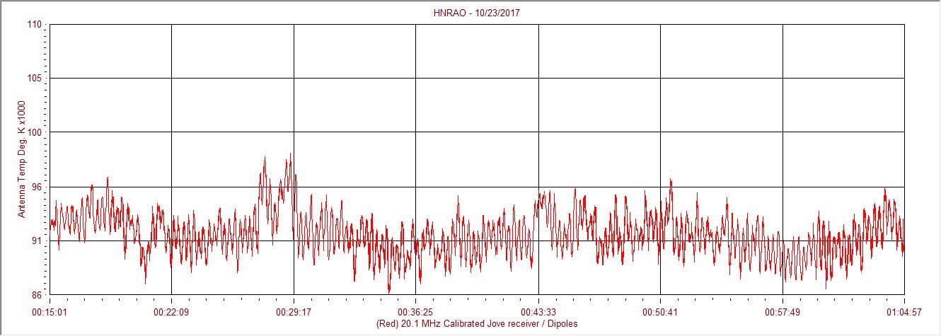

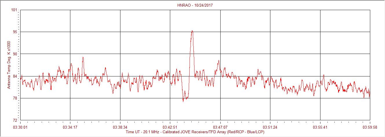
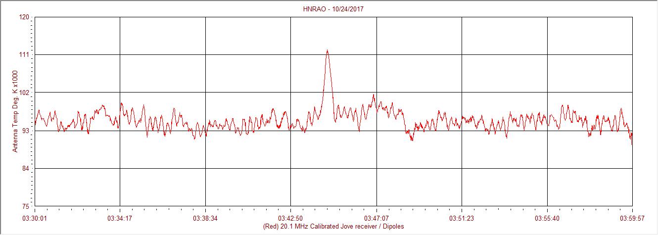

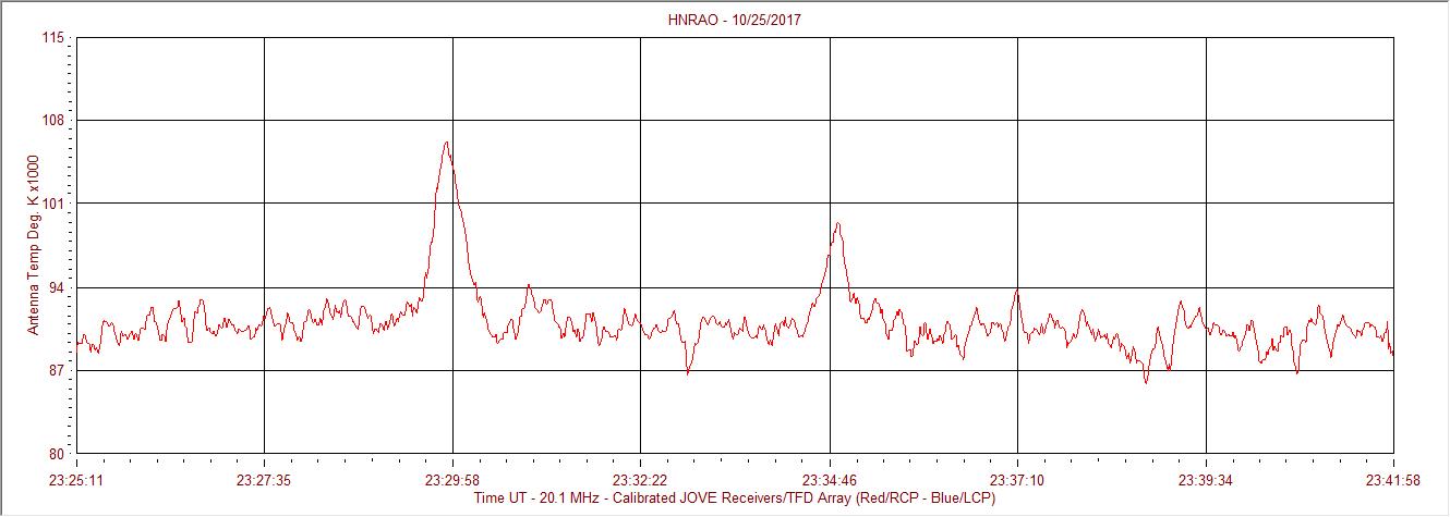
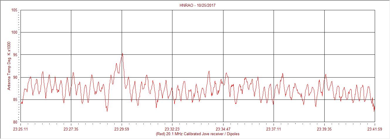
It is possible to detect weak emissions from Cas A using a Jove Radio Telescope comprising a Jove receiver, dual dipole antenna and Radio-SkyPipe software. Individual scintillation events are weak, sometimes appearing on the order of 0.5dB above the galactic background at a quiet receiving site. Cas A signals are only identifiable using this equipment during periods of signal strength enhancement caused by scintillation. In order to identify the individual scintillation events in a Radio-SkyPipe record they should be matched with scintillation features visible in a radio spectrogram. Cas A (3C461) is located at 23.4h right ascension and a declination of +58.9 deg. Because of the wide antenna beamwidths used in these observations it is possible, but unlikely, that some of the scintillation events observed were from Cygnus A (3C405) which is located at 20h RA and +40.8 deg declination.
[1] http://www.radiojove.org/SUG/Pubs/Cassiopeia A Scintillation Observed by Radio Jove Participants, Typinski et al (2014).pdf..
[2] http://kaira.sgo.fi/2012/10/ionospheric-scintillation-with-kaira.html
[3] The standard JOVE antenna is a two element phased dipole array. For these observations the standard Jove array which uses 75 ohm coax cable and a TV power combiner was converted to a system with 50 ohm coax and a 50 ohm commercial power combiner. This modification reduces calibration uncertainty. The Jove receiver is a simple direct conversion receiver for 20.1 MHz https://radiojove.gsfc.nasa.gov/..
[4] TFD Array – terminated folded dipole array comprises a pair of dipoles aligned N/S and a second pair of dipoles aligned E/W in a square configuration fed through a hybrid combiner to produce both right hand and left hand circular polarization.
[5] Radio Sky Spectrograph and Radio-SkyPipe software: http://www.radiosky.com//
The JOVE Bulletin is published twice a year. It is a free service of the Radio JOVE Project. We hope you will find it of value. Back issues are available on the Radio JOVE Project Web site, http://radiojove.gsfc.nasa.gov/
For assistance or information send inquiries to:
or
